Packet Tracer — Build a Switch and Router Network
Objectives
- Configure PCs.
- Configure a router.
- Verify end-to-end connectivity.
- Configure a switch.
- Secure remote access to the router.
Background / Scenario
Your aunt owns a small insurance agency. She recently purchased a Cisco router and switch. She has two wired PCs that need to be connect to the network. She is proud of your progress in your networking course and asked you if you would like to demonstrate your skills. Your job is to connect the devices, implement a basic configuration, and verify connectivity. After network connectivity has been verified, you will use IOS commands to retrieve information from the devices to answer questions about your network equipment. You will also configure the router for secure remote access.

Step 1:
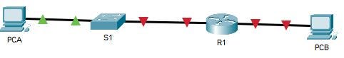
First, you will connect the devices using Copper Straight-Through cables.
- Connect R1 G0/0/1 to any port on S1.
- Connect PCA to any port on S1.
- Connect PCB to R1 G0/0/0.
Hint: In the bottom toolbar, click Connections > Copper Straight-Through cable, and then connect between the devices and ports specified above.

- PCA uses (FastEthernet0) to connect with Switch 1
- We can connect the PCA to any FastEthernet interface on Switch 1 (from FastEthernet0/2 to FastEthernet 0/10/24)
- Switch 1 uses the FastEthernet 0/1 to connect with Router 1.

Step 2:
In this step, you will assign static IPv4 addressing information to the PC interfaces. Use the information in the Addressing Table to complete the task.
- Configure the IPv4 address, subnet mask, and default gateway settings on PCA .
- Configure the IPv4 address, subnet mask, and default gateway settings on PCB .
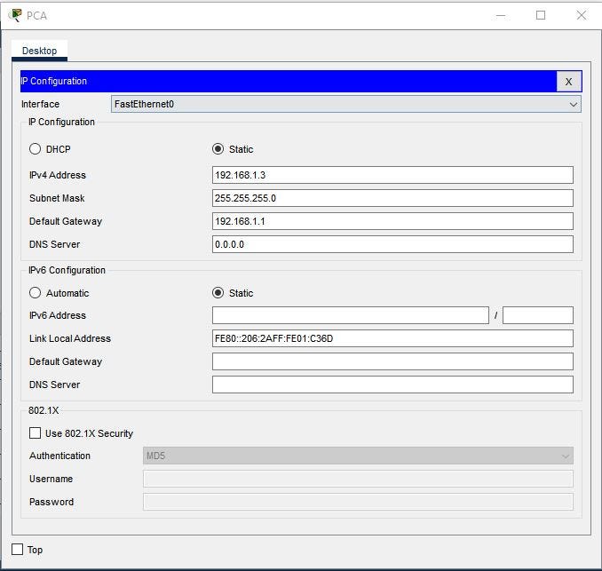
Click on PCA computer icon, on the PCA desktop click on IP Configuration

Hint: The following values are found in the Addressing Table. Enter them in the IP Configuration for PCA .
- IP Address: 192.168.1.3
- Subnet Mask: 255.255.255.0
- Default Gateway: 192.168.1.1
Click on PCB computer icon, on the PCB desktop click on IP Configuration
The following values are found in the Addressing Table. Enter them in the IP Configuration for PCB .
- IP Address: 192.168.0.3
- Subnet Mask: 255.255.255.0
- Default Gateway: 192.168.0.1

Step 3:
In this step, you will Test connectivity between PCA and PCB.
- Ping between PCA and PCB.
Hint: In the PCA Command Prompt, enter the ping 192.168.0.3 command. You can also open the PCB Command Prompt, and then enter the ping 192.168.1.3 command.

Why were the pings not successful?
- Yes
The router interfaces, which are the default gateways for each PC, have not been configured yet; therefore, the ping traffic is not being routed between the PCA and PCB networks. Note that link lights on the connections from the router are red. This indicates that the links are not functioning.
Step 4:
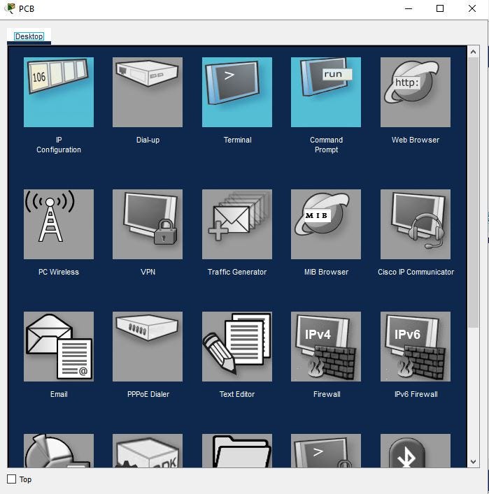
In this step, you will use the CLI tab for R1 to configure basic settings. You can connect a Console cable and access the CLI from PCA or PCB, if you wish. However, in this activity, you can also just click R1 to open it.
- Assign a hostname according to the Addressing Table.
Hint: If necessary, click R1. Then enter the following command:
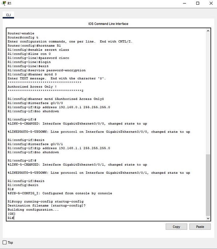
Router>enable
Router# configure terminal
Router(config)# hostname R1- Assign class as the privileged EXEC encrypted password.
Configure the privileged EXEC mode password in global configuration mode with the following command:
R1(config)# enable secret class- Assign cisco as the console password and enable login.
Enter line configuration mode in global configuration mode with the following command:
R1(config)# line con 0Configure the console password with the following command:
R1(config-line)# password ciscoConfigure the console line to require login:
R1(config-line)# login- Encrypt the plaintext passwords.
Encrypt plaintext passwords with the following command in global configuration mode:
R1(config)# service password-encryption- Create a banner that warns anyone accessing the device that unauthorized access is prohibited.
Configure a banner with the following command:
R1(config)# banner motd $Authorized Access Only!$In this example, $ is the delimiter.
- For G0/0/0, configure IP addressing according to the Addressing Table and activate the interface.
Enter interface configuration mode with the following command:
R1(config)# interface g0/0/0Configure the G0/0/0 interface with the following command with the following command:
R1(config-if)# ip address 192.168.0.1 255.255.255.0- For G0/0/1, configure IP addressing according to the Addressing Table and activate the interface.
Enter interface configuration mode with the following command:
R1(config)# interface g0/0/1
R1(config-if)# ip address 192.168.1.1 255.255.255.0
R1(config-if)# no shutdown- Save the running configuration to the startup configuration file.
R1(config)# exit
R1# copy running-config startup-config
Destination filename [startup-config]?
Building configuration...
[OK]
You can also use the abbreviated copy run start or the write mem command
Step 5:
Now, let’s test connectivity between PCA and PCB again.
- Ping between PCA and PCB.
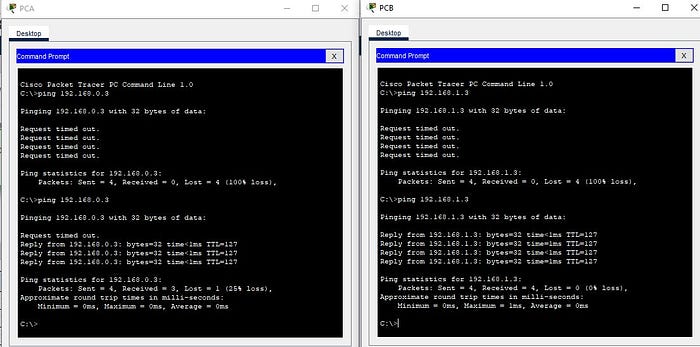
Hint: In the PCA Command Prompt, Enter the ping 192.168.0.3 command. You can also open the PCB Command Prompt, and then enter the ping 192.168.1.3 command.
Why were the pings between PCA and PCB successful?
- Yes
The router is routing the ping traffic across the two networks. The default settings for the 2960 switch will automatically enable the interfaces that are connected to devices.

Step 6:
In this step, you will use the CLI tab for S1 to configure basic settings. You can connect a console cable and access the CLI from PCA or PCB, if you wish. However, in this activity, you can also just click S1 to open it.

- Assign a hostname according to the Addressing Table
If necessary, click S1. Then enter the following command:
Switch> enable
Switch# configure terminal
Switch(config)# hostname S1- Assign class as the privileged EXEC encrypted password.
Configure the privileged EXEC mode password in global configuration mode with the following command:
S1(config)# enable secret class- Assign cisco as the console password and enable login.
Enter line configuration mode in global configuration mode with the following commands:
S1(config)# line con 0
S1(config-line)# password cisco
S1(config-line)# login- Encrypt the plaintext passwords.
Encrypt plaintext passwords with the following command in global configuration mode:
S1(config)# service password-encryption- Create a banner that warns anyone accessing the device that unauthorized access is prohibited.
Configure a banner with the following command:
S1(config)# banner motd $Authorized Access Only!$In this example, $ is the delimiter.
- For VLAN 1, configure IP addressing according to the Addressing Table and activate the interface.
Enter interface configuration mode with the following commands:
S1(config)# interface vlan 1
S1(config-if)# ip address 192.168.1.2 255.255.255.0
S1(config-if)# no shutdown- Configure the default gateway according to the Addressing Table
Configure the default gateway with the following command:
S1(config)# ip default-gateway 192.168.1.1- Save the running configuration to the startup configuration file.
Save the configuration with the following command:
S1(config)# exit
S1# copy running-config startup-config
You can also use the abbreviated copy run start or the write mem command
Step 7:
In this step, you will Secure remote access to R1.
Hint: If necessary, log back in to R1 with the password cisco, enter privileged EXEC mode with the password class.
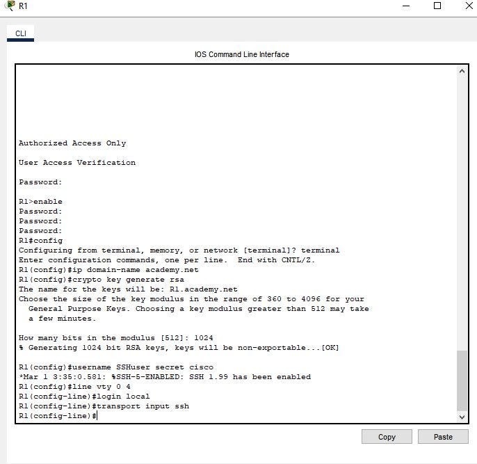
- On R1, configure the domain name as academy.net.
Enter the following command:
R1(config)# ip domain-name academy.net- Generate RSA keys with a 1024 key length
Enter the following command:
R1(config)# crypto key generate rsaEnter 1024 for How many bits in the modulus [512] question.
- Create a user with SSHuser as the username and cisco as the secret password.
Enter the following command:
R1(config)# username SSHuser secret cisco- Configure the VTY lines to use the local username database for login credentials. The VTY lines should only allow SSH for remote access.
Enter the following command:
Enter the following command:
R1(config)# line vty 0 4
R1(config-line)# login local
R1(config-line)# transport input ssh
Step 8:
Now, let’s verify SSH remote access.
- From PCA or PCB, use the Command Prompt to establish a secure session with R1. At the prompt, use the ssh command.

Click either PCA or PCB, open the Command Prompt, and then enter the following command:
C:\> ssh -l SSHuser 192.168.1.1The password is cisco.
Reflection Question:
- If the G0/0/1 interface status is administratively down, what interface configuration command would you use to activate the interface?
- R1(config-if)# no shutdown
2. What would happen if you had incorrectly configured interface G0/0/1 on the router with an IP address of 192.168.1.2?
- PCA would not be able to ping PCB. This is because PCB is on a different network than PCA. A default-gateway router is required to route these packets. PCA is configured to use the IP address of 192.168.1.1 for the default-gateway router, but this address is not assigned to any device on the LAN. Any packets that need to be sent to the default-gateway for routing will never reach their destination.
Congratulations!! You have successfully connected devices, implemented basic configurations for PCs, a router, and a switch, and then secured and verified remote access to the router.
Summary
In this activity, you have accomplished the following learning objectives:
- Connected and configured PCs.
- Configured a router.
- Verified end-to-end connectivity.
- Configured a switch.
- Secured and verified remote access to the router.
References:
Cisco Packet Tracer: https://learningnetwork.cisco.com/s/packet-tracer-alternative-lab-solutions
